
Before You Start
Please read the entire installation manual. The thermostat will need to be correctly wired and configured for proper operation. Basic HVAC configuration can be performed from the thermostat touchscreen, and advanced settings are accessed via your network and the Internet.
Table of Contents
- Thermostat Callout
- Installation
- Mount Thermostat Backplate
- Basic Wiring Diagram
- Terminal Connection Callouts
- Independent Power Source
- Wiring Diagram Reference Chart
- Reattach Faceplate
- Thermostat Setup
- Touchscreen User Menu
- Touchscreen Installer Menu
- Connect To Network
- Additional Settings and Features
- Programming The Thermostat
- External Connections
- Thermostat Reset Modes
- Five (5) Year Limited Warranty
- Specifications
Introduction
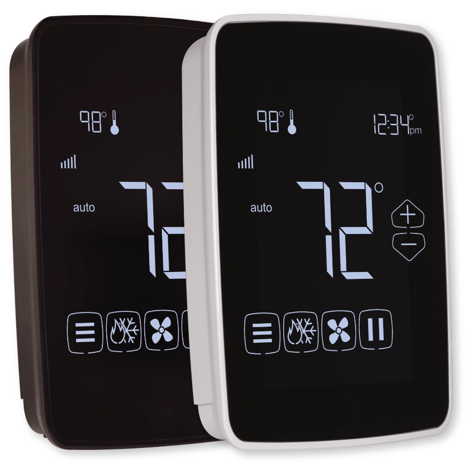
The J5-WIFI thermostat is a network-connected color touchscreen thermostat with an advanced remote sensor bus, designed for new or replacement commercial or residential applications. It supports up to 3 Heat / 2 Cool heat pumps and 2 Heat / 2 Cool conventional systems. Internal webpages help deliver a near-effortless setup of your daily schedules (4 events per day), and up to 40 Special and 40 Calendar Events. The unique scheduling structure also supports the powerful features of adjustable temporary override times, temperature ranges, occupied and unoccupied events, keypad lockout, and many more features.
All J-Series Thermostats support NetX-Cloud™.
Core Features
- 4 independent schedules per day
- 40 Calendar Event Schedules
- 40 Special Event Schedules
- Integrated Humidity Sensor
- Integrated Weather with Current Conditions & 7-Day Forecasts
- Email & Text Message Alerting for 4 Recipients
- Alerts include Hi/Lo Temps for Indoor, Outdoor, Inefficient Equipment Run, Change Filter Notifications.
What is in the box?
(1) J-Series Thermostat Faceplate
(1) Wiring Backplate
(2) 3/16 Drywall anchors
(2) Mounting Screws
(1) Installation Manual
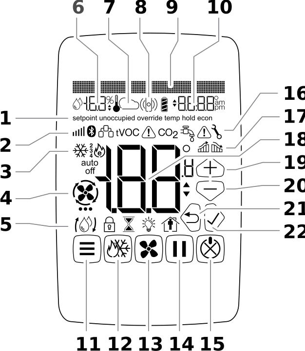
Thermostat Callout
- Special Status Notification
- Secondary Notification Icons
- Current Equipment Mode Indicators
- Fan Status
- Secondary Status Icons
- Remote Sensor Value (humidity and temperature)
- Remote Sensor Icons (temperature, indoor, outdoor icons)
- Occupancy Sensor Icon
- Dot Matrix Display
- Clock Display
- Menu Button
- Mode Button
- Fan Button
- Hold Button
- Resume/Cancel/Power Button
- Secondary Notification Icons
- Adaptive Recovery Icons
- Current Temperature Display
- Up Button (Up Arrow)
- Down Button (Down Arrow)
- Back Button (Left Arrow)
- Accept Button (Right Arrow)
Installation
Thermostat Location
To ensure proper operation, the thermostat should be mounted on an inside wall in a frequently occupied area of the space. In addition, its position must be at least 18” (46 cm) from any outside wall, and approximately 5’ (1.5 m) above the floor in a location with freely circulating air of an average temperature.
Be sure to avoid the following locations:
- Behind doors or in corners where freely circulating air is unavailable
- Where direct sunlight or radiant heat from appliances might affect control operation
- On an outside wall
- Adjacent to, or in line with, conditioned air discharge grilles, stairwells, or outside doors
- Where its operation may be affected by steam or water pipes or warm air stacks in an adjacent partition, or by any unheated/uncooled area behind the thermostat
- Where the operation may be affected by lighting dimmers
- Where the operation will be affected by the supply air of an adjacent unit
- Near an electrical source interference such as arcing relay contacts
Mount Thermostat Backplate
BEFORE YOU BEGIN: Turn off the power to the HVAC equipment.
TIP: If you are replacing an existing thermostat, take a picture of the thermostat wiring for reference.
1. From the factory, the thermostat faceplate is not firmly connected to the backplate. While holding the thermostat, firmly near the bottom, gently pull apart the backplate from the faceplate.
2. Place the rectangular opening in the backplate over the equipment control wires protruding from the wall. Use the backplate as a template and mark the location of the two mounting holes.
3. Use the supplied anchors and screws for mounting on drywall or plaster; drill two 3/16” (5mm) diameter holes at the marked locations; tap the nylon anchors flush to the wall surface and fasten the backplate using the supplied screws.
WARNING: Do not over-tighten the screws!
4. Connect the wires from your system to the thermostat terminals as shown in the Wiring Diagrams section of this manual. Carefully dress the wires so that any excess is pushed back into the wall cavity or junction box. Ensure that the wires are flush with the plastic backplate. The access hole should be sealed or stuffed to prevent drafts from affecting the thermostat.
Basic Wiring Diagram
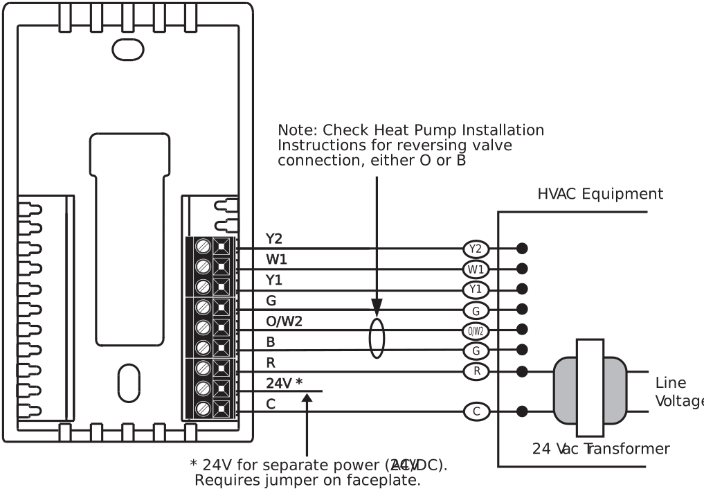
Terminal Connection Callouts
Y2: | Energizes the compressor for second-stage cooling, or for heat pumps, either second-stage heating or cooling |
W1: | Energizes the heater for first-stage heating, or for heat pumps, auxiliary /emergency heat |
Y1: | Energizes the compressor for first-stage cooling, or for heat pumps, either first-stage heating or cooling |
G: | Energizes the fan circuit with a call for heating or cooling |
R: | Independent Switching Voltage from HVAC equipment |
24V: | 24Vac |
24V(c): | 24Vac Common |
O/W2: | Energizes the heater for second-stage heating, or for heat pumps, energizes the reversing valve in cooling mode |
B: | Energizes the reversing valve in heating mode |
Independent Power Source (Optional)
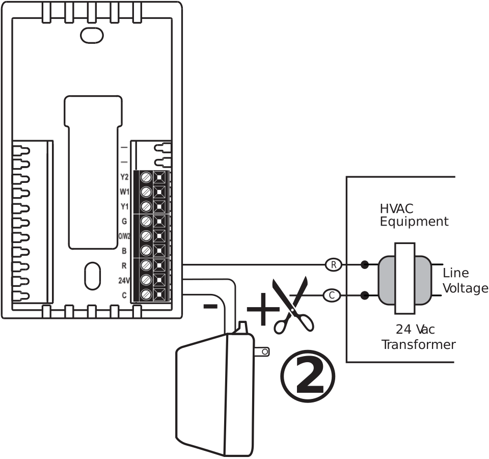
In situations where power from the HVAC hardware does not meet the needs of the J-Series thermostat. You can power the J-Series thermostat independently of the HVAC unit. Network Thermostat 24 VAC Transformer has the capability to power six J-Series thermostats. Follow the steps below to install a separate power source.
Remove the jumper on the faceplate.
Place the separate transformer 24V wire in the 24V terminal.
Place the separate transformer 24VAC (Common) wire in the
C terminal.
The common from the equipment does not connect to the thermostat. This can cause a ground loop and issues.
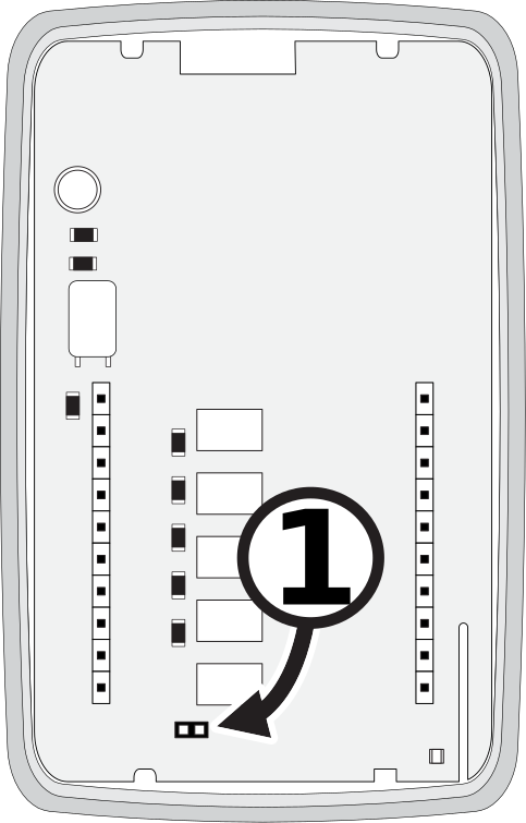
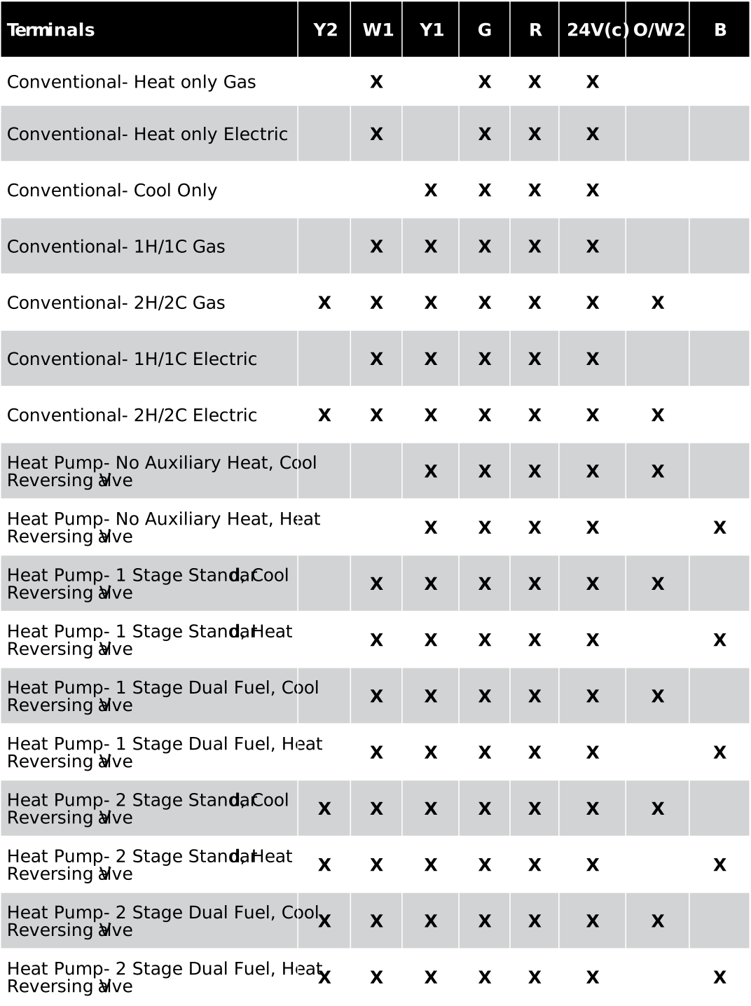
Wiring Diagram Cross Reference Chart
The chart below lists the connections needed for the most common applications. Refer to the Basic Wiring Diagram for where to connect appropriate wires.
Reattach Faceplate
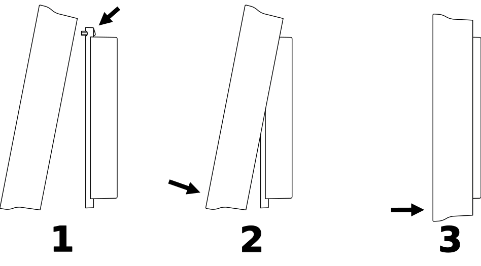
- Reattach the faceplate to the backplate by placing the top of the faceplate over the top lip of the backplate.
- Gently swing the thermostat down and press on the bottom center edge until it snaps in place. This is a tight connection, and it may require a little wiggle to align the pins on the faceplate with the screw terminals on the backplate before it snaps into place.
- Reconnect power to the HVAC equipment. You are now ready to configure your thermostat for operation.
WARNING: Your thermostat is NOT ready to use. You must complete the Thermostat Setup section before using the thermostat. Failure to do this can result in damage to your equipment.
Thermostat Setup
The Dot Matrix Display will provide feedback on the User Menu or Installer Menu configuration and selected options. The UP and DOWN Buttons are used to select parameters, while the LEFT ARROW (Back Button) and RIGHT ARROW (Accept Button) are used to accept settings and navigate through the menu. You can use the CANCEL BUTTON to leave the User or Installer Menu at any time.
Touchscreen User Menu Settings
Tap the MENU Button on the lower left of the thermostat touchscreen to access the User Menu. The Dot Matrix Area will guide you through the User settings. To save a setting and navigate to the next menu item, press the CHECKMARK Button (Right Arrow). To return to the previous menu item, press the BACK Button (Left Arrow). Use the UP and DOWN Buttons to select from the available options for each setting.
Brightness - Screen Brightness
Select the brightness of the touchscreen display.
Options: Auto (default), High, Medium, Low
Display Complexity
There are three different resting display options.
Options:
- Full: (default) Shows the entire screen all the time
- Minimal: if nothing is detected by the sensor for 5 seconds, only the room temperature is shown.
- Dark: if nothing is noticed by the sensor for 5 seconds, the whole screen goes blank.
Adjust Clock - 12Hr or 24Hr Clock
Select between AM/PM or 24H time display. 12 Hr is the default.
°F or °C Temperature Display
Select between °F (Fahrenheit) and °C (Celsius) temperature display. °F (Fahrenheit) is the default.
Touchscreen Installer Menu
Press and hold the Menu Button D on the lower left of the thermostat touchscreen for 5 seconds to access. Installer Menu will briefly display in the Dot Matrix Area, followed by Conventional/HP. To save a setting and advance to the next menu item, press the Checkmark Button M (Right Arrow). To return to the previous menu item, press the Back Button L (Left Arrow).
Conventional / Heat Pump
Select between Conventional and Heat Pump operation. Conventional is the default.
NOTE: If Conventional is selected, proceed to Stages Cool. If Heat Pump is selected, proceed to # of Compressors.
Stages Cool
Select between 1 and 2 Stages Cool. The value is displayed in the main display. The default is 1.
Stages Heat
Select between 1 and 2 Stages of Heat. The value is displayed in the Main Display. The default is 1.
Gas or Electric Heat
Select between Gas and Electric operation. Gas heat is the default.
NOTE: If you selected Conventional Heat, proceed to Minimum On Time.
# of Compressors
Select between 1 and 2 Stage Compressor. The value is displayed in the main display. The default is 1.
Enable Aux/EHeat
Select between Aux/EHeat Mode On (default) and Aux/EHeat Mode Off.
NOTE: If the Aux/EHeat ON is selected, proceed to Heat Pump Option. Otherwise, proceed to the Minimum On-Time option.
Heat Pump Option
Select between HP Regular (default) and HP Dual Fuel.
If needed, the thermostat will perform the function of a fossil fuel kit. When HP Dual Fuel is selected, the thermostat will turn off the compressor with a call for AUX heat. The HP Regular option will allow the compressor and AUX heat to run simultaneously.
Minimum On Time
Select from 0 up to 5 Minutes. The value is displayed in the main display. 0 Minutes is the default. The system will operate for a minimum of 0 minutes to 5 minutes, depending on your settings.
Minimum Off Time
Select between 2 to 5 Minutes. The value is displayed in the main display. 2 Minutes is the default. The system will allow equipment recovery for 2 to 5 minutes before turning it on again. This is also known as short-cycle protection.
Screen Saver
To maximize screen live, the J-Series thermostat includes a screen saver function. Never is the default. Pressing the arrow down will select Unocc which will turn off the screen when the thermostat determine the room in unoccupied. Additionally, pressing the up arrow will access a timer for the screen saver from 10 to 60 minutes in 10 minute increments.
CO2 Display
When installed with a NT-MOD-CO2, module, you can display the current CO2 levels in the thermostats area. Choices are
CO2 Alert
For CO2 alerts, you can set the threshold of the alert from 500 to 2000ppm in 50 ppm (Parts Per Million) increments. The default value is 1100ppm
Clear CO2
Select when to reset the maximum recorded CO2 level. It can be reset at Midnight every night, never or right now in the Installation Menu.
Calibration Offset
This will allow the thermostat onboard sensor to be decalibrated up to ± 6 ˚F.
Adaptive Recovery
Select On (default) or Off. When this is enabled, the thermostat will anticipate when to turn on the heating or cooling system before the start of a schedule to achieve the desired setpoint temperature by the beginning of the schedule.
Fan Purge
Select between Off, 30, 60, 90, and 120 Seconds. Off is the default.
1st Stage Differential
Select between 1-6˚F (0.5-3˚C). The value is displayed in the main display. 1˚F (0˚C) is the default. The 1st Stage Differential is the temperature degree change required before the thermostat responds.
2nd Stage Differential
Select between 1-6˚F (0.5-3˚C). The value is displayed in the main display. 3˚F (1.5˚C) is the default.
2nd Stage Delay
Select between 5-40 Minutes. The value is displayed in the main display. 20 Minutes is the default.
A NOTE: The following options only apply to multi-stage heat pump configuration.
Aux Heat Differential
Select between 1-6˚F (0.5-3˚C). The value is displayed in the main display. 1˚F (0.5˚C) is the default.
Aux Heat Delay
Select between 5-40 Minutes. The value is displayed in the main display. 20 Minutes is the default.
High & Low Balance Point Configuration
If the thermostat is being used as a Heat Pump thermostat and current weather conditions are enabled or an outdoor sensor is connected to the remote sensor terminals, the thermostat can be configured to disable the use of auxiliary heat during warmer weather and to lock out the compressor during colder weather. If the weather conditions are enabled the high and low balance point settings are available in the installer menu.
B TIP: Refer to the manufacturer’s heat pump equipment manual for temperature cut-offs on the equipment.
Low Balance Point
Select between -54˚F to 39˚F (-48˚C to 4˚C). The value is displayed in the main display. This will lock out the heat pump at the selected outdoor temperature. The default value is -54˚F (-48˚C).
High Balance Point
Select between 41˚F-118˚F (5˚C-48˚C). The value is displayed in the main display. This will lock out the auxiliary heat at the selected outdoor temperature. The default value is 118˚F (48˚C).
Temporary Override (Up to 24 hours)
Change the temperature setting temporarily without affecting the schedules, both occupied and unoccupied. Use the Up J and Down K Buttons to adjust the temperature within the minimum and maximum range. This temperature will be maintained for the duration set by the Override Timer. To cancel, simply press the Cancel Button. I
Temporary Override During Lockout (Up to 24 hours)
Change the temperature setting temporarily without affecting the schedules, even though the keypad is locked. Use the Up J and Down K Buttons to adjust the temperature limited to the Temperature Override Range setting. This temperature will be maintained for the duration set by the Override Timer. To cancel, simply press the Cancel Button. I
A NOTE: If running an OCCUPIED schedule, the currently occupied setpoint will be shown, and if running an UNOCCUPIED schedule the thermostat will revert to the most previous OCCUPIED schedule setpoints.
Set Clock
If enabled under the Allow Clock Sched section in the Installer Menu, you can set the clock by tapping on the time on the upper right of the display. Then follow the on-screen menu prompts.
Set Schedule
If enabled under the Allow Clock Sched section in the Installer Menu, the Schedules can be edited from an unlocked thermostat by pressing and holding the Pause button until the Set Schedules Interface is displayed on the faceplate. Then follow the on-screen prompts.
Auxiliary/Emergency Heat Indicator Q
The thermostat is equipped with the Emergency Heat icon Q in the Main Status Icons area on the faceplate which indicates when the system has engaged auxiliary heat mode or emergency heat mode.
Random Restart
After a power failure, the thermostat will delay the heating/ cooling equipment start-up by 1-24 seconds. When multiple NetX™ J-Series thermostats are used, this minimizes the ‘in rush’ current (electric power usage) as it reduces the number of HVAC units that will be turned on simultaneously.
Power Failures
This NetX™ J-Series has an internal power backup that will last approximately several days. If the thermostat experiences a power outage less than this time, all functions will resume as soon as power is restored. If the power outage lasts longer, upon power restoration the J-Series thermostat will recover depending on a few factors.
Time is set via NTP (Network Time Protocol) time server.
When the power is restored and the thermostat connects to the Internet, the thermostat will resume the normal programmed operation.
Time is set manually
When power is restored, the clock will flash 12:00 and will operate in Manual Mode until the time is set.
After the time has been set, the thermostat will resume the normal programmed operation.
On-board Data Logging with Sub-Metering Support
The NetX Platform provides reliable deep-data analysis for runtimes and all thermostat operations. This data can be used to perform sub-metering analysis to bill tenants according to actual HVAC usage for heating and cooling. Onboard memory supports approximately 14 days of records.
Temporarily Unlock Faceplate
When the thermostat screen is placed on the locked, you can temporarily bypass the Lock Screen by entering the 4-digit PIN. To temporarily unlock, follow the steps below.
Press the bottom left area of the touchscreen where the Menu Button D is usually located. Temporary Unlock will display in the Dot Matrix Display.
The Dot Matrix area will then display Enter PIN: 0 0 0 0. Use the Up J and Down K Buttons to select the first digit in the pin code. Press the Accept Button M (Right Arrow) to Enter the first digit.
Repeat Step 2 for the next three digits.
When you enter the correct PIN, the thermostat will return to the main screen and display a countdown timer Unlock: 30 min left in the Dot Matrix Display To re-lock the screen, press the Cancel Button I on the right.
C WARNING: If you enter the incorrect PIN, Wrong PIN will display in the Dot Matrix display. After 3 wrong attempts, the thermostat will return to the main screen and will not allow another attempt for 5 minutes.
Connect Thermostat To Network
Before You Begin
Important: Do not install the thermostat until you have gathered all required login credentials and network information.
Set Up Your Primary NetX-Cloud Account
Choosing the correct login credentials is an important first step in the NetX-Cloud setup process. These credentials will serve as the primary administrator account for your organization.
We strongly recommend using a dedicated company email address rather than a personal, employee, contractor, or installer email address. This helps ensure continued access to your account, even if personnel changes occur.
Examples:
netx@yourcompanydomain.com
facilities@yourcompanydomain.com
Guidelines:
Use a dedicated company email address for the primary account (examples above)
Create a strong, secure password and store it in a safe location accessible to authorized personnel.
•DO NOT USE a personal or employee email address.
•DO NOT USE a contractor or installer email address for the primary account.
Add Secondary Email Addresses
After your NetX-Cloud account has been created, you can add additional email addresses for billing and thermostat management through the Cloud Customer Profile page.
We recommend adding:
An accounting email address for billing notifications.
A facility manager or maintenance email address for thermostat alerts and disconnect notices.
Many organizations do not actively monitor the primary administrator's email account. Adding secondary contacts helps ensure important notifications are received by the appropriate personnel.
Gather Your Network Information
For a Wi-Fi CloudConnect™ installation, you will need the following information:
SSID (Wi-Fi network name)
Wi-Fi password
Security type (WPA2, WPA3, etc.)
Before beginning installation, verify that this information is available. If you do not know these settings, they can typically be found:
In your router's wireless settings.
On a label attached to the router.
By contacting your network administrator or IT department.
Networks With Enhanced Security
If your organization uses enhanced network security or restricts incoming and outgoing ports, additional configuration may be required for proper communication between the thermostat and the NetX-Cloud platform.
Upon request, we can provide a list of the required ports and communication settings. For security purposes, this information is available only after a signed NDA has been submitted by your IT administrator.
To request this information, please submit a support ticket: Tech Support (support.networkthermstat.com)
Enter SoftAP Mode - First-Time Power-Up
On initial power-up or if the thermostat networking has not been configured, the thermostat will start in SoftAP mode. It will remain in SoftAP mode until the thermostat is rebooted with properly configured Wi-Fi credentials or no activity is detected on the thermostat for 10 minutes. You will know if you are in SoftAP mode when the following conditions are met:
The Dot Matrix display reads Join NetX-XXXXXX where XXXXX is the last 6 characters of MAC ID
The Wi-Fi icon and the lower right button will be flashing in 1-second intervals. (Green highlighted areas)
Pressing the lower right flashing button at this time will exit the SoftAP mode without saving any network configurations.
A NOTE: For security purposes, SoftAP is active for only 10 minutes with no activity. If the thermostat drops out of SoftAP mode, see the Troubleshooting: Thermostat Reset Modes section below and initiate a 'Network Reset'. This will restart SoftAP.
A NOTE: If the thermostat is LOCKED, you will be required to UNLOCK (either permanently or temporarily) the thermostat before SoftAP commissioning is allowed. When LOCKED, none of the SoftAP commissioning icons above are turned on and the thermostat continues to operate 'normally'.
Connect To The Wi-Fi Thermostat Using ‘SoftAp’ Mode & Setting Local Wi-Fi Network
If your computer is connected to the internet with an ethernet cable, it is recommended to temporarily disconnect this cable during this step. Using any Windows PC, Apple Computer, or smartphone with a Wi-Fi radio and a web browser, search for the Wi-Fi network with the SSID name NetX-XXXXXX that matches the Dot Matrix Display.
Connect to the NetX-XXXXXX network. This is an open network and does not have a password. It may take up to a full minute for your computer to connect to the thermostat.
Use any current release browser (Chrome, Firefox, or Safari) to navigate to 192.168.7.1. This is the SoftAP address for the thermostat.
B TIP: For information on an extra step needed for using SoftAP on android devices, click the link below.
https://networkthermostat.com/app-notes/soft-ap-android-tips
When the device connects to the thermostat, the screen below will be displayed in the browser.
Enter your Wi-Fi Network Information:
1.On the top of the screen click “Scan for Networks”.
2.A list of available Wi-Fi networks will appear.
3.Select your network.
4.The Security Mode will be automatically selected.
5.Enter the wireless network's Pass Phrase.
By default, “Enable DHCP will be checked. Unchecking the box will expose the parameters required for static IP operation.
Click 'Save & Reboot'. Depending on the type of wireless network, it may take up to a few minutes to make a secure network connection.
A NOTE: After clicking “Save & Reboot” the thermostat will reboot while displaying the following flashing at a 1-second interval:
Dot Matrix - “Waiting… “ blinking
Wi-Fi Icon blinking
Bottom right button blinking
(Green highlighted areas are blinking)
If the network parameters are accepted, for 5 seconds you will see “Wi-Fi Connected” on the Dot Matrix and the Wi-Fi icon illuminated. After 5 seconds, the thermostat will return to the normal display. If the process is not successful, depending on the failure mode, you will see one of the following results:
A NOTE: If you experience either Wi-Fi or DHCP failure, refer to the Troubleshooting section at the end of these instructions.
Reconnect Your Computer To Wireless Network
While the thermostat is rebooting (it will only take a few seconds), use your set up device’s network settings to connect to the wireless network (SSID) using the password credentials used in the network setup.
The screenshot to the right shows typical PC wireless networks. In this case, the thermostat network has the SSID name NETGEAR67. When the thermostat is properly connected to the wireless network, the Green LED will be on steady (indicating the thermostat is connected to the network you selected).
B TIP: If a hardwire ethernet cable was removed in Step 4, it can be plugged back into the computer now.
Retrieve Your IP address Via the Faceplate
The IP address can be retrieved from the faceplate of your thermostat by accessing the Installer Menu.
1.With an unlocked faceplate (the lock icon is not on), press and hold the Menu Icon for 5 seconds to enter the Installer Menu. Do not release the Menu button until the Installer text displays in the Dot Matrix of the faceplate.
2.Next, press the hidden button, located to the left of the Checkmark button. This will retrieve the device name. The device name will be displayed in the Dot Matrix of the faceplate.
3.Use the Checkmark button and the Return button to switch between the Thermostat Name, IP Address, and MAC Address. WRITE DOWN THE IP ADDRESS. To exit the menu, tap the Cancel button at the bottom right of the display.
B HINT: Use the Checkmark and Return buttons are denoted by the red arrows.
Configure Credentials
Enter the IP Address in your browser, then enter your username (a real email address) and password for the thermostat. Click on the “Save Credentials” button to save your information. You will be taken to the login page for the thermostat. For CloudConnect™ configuration go to the URL in the next step.
Additional Settings and Features
In addition to the User Menu and Installer Menu The J-Series thermostat has additional options that can be set using the built-in web pages or via our cloud interface. Please refer to this online guide for setting these additional parameters. Unless otherwise noted, these additional settings are available under the Configuration menu tab of the built-in web pages. Log in to your thermostat via the credentials you added above.
Basic Config Page
Override Timer
On the Basic Configuration page, you will be able to adjust the length of a temporary override condition from 0 minutes to 24 hours, in 10-minute increments. The default override time is 8 hours.
Temperature Override Range (During Lockout)
On the Basic Configuration page, this setting adjusts the temperature variance allowed from the scheduled setpoint when the faceplate is locked. The range is from ±2˚F (1˚C) to ±8˚F (4˚C). The default is ±3˚F (1.5˚C).
HVAC Settings Page
Temperature Calibration Offset
The thermostat is pre-calibrated at the factory, but in some installations, lack of airflow at the sensor or proximity to other warming or cooling sources may cause the temperature to be off by a few degrees. The J-Series thermostat includes a temperature calibration offset with a range of ±6˚F (3˚C) in 0.2˚F (0.1˚C) increments. The Temperature Calibration Offset is on the HVAC Settings web page of the thermostat.
Lock Screen
The J-Series thermostat can restrict and lockout certain functions available from the faceplate. The Lock Screen can be activated from the HVAC Settings web page on the thermostat. When engaged, you can set a 4-digit pin code that can be used to temporarily unlock the faceplate for 30 minutes.
Programming The Thermostat
This NetX™ thermostat product has factory default programs as indicated below. Based on energy-saving guidelines and recommendations for residential use, these settings can reduce heating/cooling expenses by as much as 33%.
External Connections
This thermostat is intended to be used as a Communicating Programmable Thermostat, with changes to the thermostat schedules accomplished over a computer interface via:
1.NetX-Cloud™ Internet-Based Cloud Service
2.PCConnect™ Local Network & Port Forwarded Access
3.DirectConnect™ Integrated Web Server for Connectivity from Any Modern Web Browser
4.Integrated NetX™ API, Supports 3rd Party Apps
5.BACnet Integration Option
6.Modbus Integration Option
OPTIONAL - Connect To Your Thermostat Using NetX-Cloud™ Service
Using a desktop browser, go to the URL
https://netx-cloud.com. Log in with the same username and password you used above.
Once logged in, you will see a dashboard with your thermostats on the right and a drop-down menu on the left. Expand the menu under “New Site” and “Default.” Expand the thermostat (click the ‘+’ to the left of the thermostat name) and navigate to the Configuration page.
A NOTE: Thermostats are automatically enrolled with free NetX-Cloud™ for 30 days.
A NOTE: For more information on NetX-Cloud™ contact us at https://networkthermostat.com/contact for more information.
OPTIONAL - Edit your Thermostat Configuration
Enter a unique descriptive name in the Thermostat Name box
A NOTE: Thermostat names may have a maximum length of 15 characters with no spaces.
Click the Apply button for the thermostat name to be saved.
Enter the Site Name.
Enter your address with your Zip Code. Adding the Zip Code allows the thermostat to access your current weather and forecast information)
Click the Apply button.
Make any additional adjustments as needed.
C ATTENTION: Make sure to click the appropriate Apply button located in the same block as the parameters you have adjusted. The thermostat will not update its parameters unless the appropriate Apply button is clicked.
DirectConnect™ Application
Direct access to the thermostats settings can be accessed the thermostat’s embedded web pages. To make the process easier, your thermostat can be configured for a static IP address. Under Configuration/Network Settings,
1.Disable the DHCP
2.Set the IP Address
3.Save and Reboot settings
This behind firewall feature will enable direct access to your thermostat without leaving your network.
Troubleshooting Wi-Fi Installation
A NOTE: If you experience either Wi-Fi or DHCP failure, power off the thermostat and start the process again.
Wi-Fi Failure
Dot Matrix - “Connection Failed… “ on solid
Wi-Fi Icon blinking
Bottom right button blinking
The thermostat will reboot into SoftAP mode
(Green highlighted areas are blinking)
DHCP Failure
Dot Matrix - “DHCP Failed… “ on solid
Wi-Fi Icon blinking
Bottom right button blinking
The thermostat will reboot into SoftAP mode
(Green highlighted areas are blinking)
Thermostat Reset Modes
There are four (4) types of 'resets' incorporated into J-Series Wi-Fi thermostats. The reset modes are accessed by entering the Installer Menu on the thermostat faceplate. With an unlocked faceplate (the lock icon is not on), press and hold the Menu Icon for 5 seconds to enter the Installer Menu. Do not release the Menu button until the Installer text displays in the Dot Matrix of the faceplate. Once there, press the right-side checkmark button until you reach the “Exit Menu” section of the Installer Menu. Using the Up and Down buttons you can access the different thermostat reset levels. Refer to the list below to select the appropriate one for your situation.
•Network Reset: Resets the Wi-Fi (network) information to SoftAP so the thermostat can join a network. Accepting this reset will return the Network Settings to thermostat defaults. User Info and HVAC Controls will remain unchanged.
•User Info Reset: Resets all User information except the HVAC Controls. Accepting this reset will return the User Info to factory defaults. HVAC Controls and the Network Settings will remain unchanged.
•HVAC Reset: Resets all HVAC Controls. The number in the Clock Position displays the number of times the microprocessor has rebooted since the last Factory Reset. Accepting this reset will return the HVAC Settings to thermostat defaults. User Info and Network Settings will remain unchanged.
•Factory Reset: Reset the entire thermostat back to factory defaults. The number in the Clock Position displays the number of times the microprocessor has rebooted since the last Factory Reset. Accepting this reset will reset all settings in the thermostat and additionally will clear the internal Datalog and the number of times the thermostat microprocessor has rebooted since the last Factory Reset.
A NOTE: Factory reset is best used if moving a thermostat to a different location. Take care in using this option as the datalog information cannot be recovered.
Five (5) Year Limited Warranty
Network Thermostat™ warrants to the original purchaser that this product will be free from defects in workmanship and materials for a period of five years from the date of purchase with proof of purchase.
Warranty Limitations
This warranty begins on the date of purchase.
Warranty is Void if:
The date code or serial number is defaced or removed.
The product has a defect or damage due to product alteration, connection to an improper electrical supply, shipping and handling, accident, fire, flood, lightning, or other conditions beyond the control of the manufacturer.
The product is not installed according to the manufacturer’s instructions and specifications.
Five (5) Year Limited Warranty (CONT)
Owner’s Responsibility
Provide proof of purchase.
Provide normal care and maintenance.
Pay for freight, labor, and travel.
Return any defective product.
In no event shall the manufacturer be liable for incidental or consequential damages.
This warranty gives you specific legal rights and you may have others that vary by state and/or province. For example, some states and/or provinces do not allow the exclusion or limitation of incidental or consequential damages, so this exclusion may not apply to you. The manufacturer’s continuing commitment to quality products may require a change in specifications without notice.
CA Title 24 Requirements
This thermostat meets the Joint Appendix 5 (JA5) requirements for Occupant Controlled Smart Thermostat (OCST) certification of the California Energy Commission (CEC).
FCC Regulatory Information
This equipment has been tested and found to comply with the limits for a Class B digital device, pursuant to part 15 of the FCC Rules. These limits are designed to provide reasonable protection against harmful interference in a residential installation. This equipment generates, uses, and can radiate radio frequency energy, and if not installed and used in accordance with the instructions, may cause harmful interference to radio communications. However, there is no guarantee that interference will not occur in a particular installation. If this equipment does cause harmful interference to radio or television reception, which can be determined by turning the equipment off and on, the user is encouraged to try to correct the interference by one or more of the following measures:
• Reorient or relocate the receiving antenna
• Increase the separation between the equipment and the receiver
• Connect the equipment to an outlet on a circuit different from that to which the receiver is connected
• Consult the dealer or an experienced radio/TV technician for help
Copyright Notice
This manual and its content are copyright of Network Thermostat -
© Network Thermostat 2026. All rights reserved.
BACnet™ is a trademark of ASHRAE
Modbus™ is a registered trademark of Schneider Automation Inc.
Specifications