

Table of Contents
- Before You Start
- What is in the box?
- Remote Sensor Callout
- Mounting Locations
- Install Steps
- Using NT-URS as Humidity Sensor
- ADDING EXTERNAL SENSOR PROBES
- NT-URS AS AUX1, AUX2, OR AUX3 SENSOR
- One (1) Year Limited Warranty
- Specifications
- LED Status
- Wiring Diagram
- Compatibility Chart
- DIP Switch SETTINGS
Before You Start
Please read the entire installation manual. The NT-URS will need to be correctly wired and configured for proper operation.
For product information on the NT-URS, Click NT-URS Product Info
Introduction
The Network Thermostat NT-URS remote sensor is designed to sense air temperature and/or humidity at locations remote to the X-Series thermostats. There are several individual temperature sensor types plus one humidity sensor with two options. One of each type of sensor can be used on the X-Series thermostats, plus up to six (6) remote INDOOR sensors to provide automatic averaging for the space temperature. The sensors are supplied with an easy-to-install surface mount enclosure. Optional 2-wire surface mount sensor and flush mount sensor are available for indoor, plus an outdoor probe and various other probes are available.
What is in the box?
- (1) NT-URS Universal Remote Sensor
- (2) 3/16” Drywall anchors
- (2) Mounting Screws
- (1) Installation Manual
Remote Sensor Callout

1 Number of Sensors Jumper
2 Wiring to Thermostat
3 Wiring to an external probe
4 Remote Sensor Configuration DIP Switches
5 Diagnostic LED
Mounting Locations
For proper operation, the sensor should be mounted on an interior location.
For room temperature sensing, it must be at least 18” (46 cm) from any outside wall, and approximately 5’ (1.5 m) above the floor in a location with freely circulating air of an average temperature.
Be sure to avoid the following locations:
- Behind doors or in corners where freely circulating air is unavailable
- Where direct sunlight or radiant heat from appliances might affect control operation
- On an outside wall
- Adjacent to, or in line with, conditioned air discharge grilles, stairwells, or outside doors
- Where its operation may be affected by steam or water pipes or warm air stacks in an adjacent partition, or by any unheated or uncooled area behind the thermostat
- Where operation may be affected by lighting dimmers
- Where operation will be affected by the supply air of an adjacent unit
- Near electrical source interference such as arcing relay contacts
Install Steps
TIP: If you are replacing an existing sensor, take a picture of the wiring for reference.
Install the X-Series thermostat according to the instruction manual supplied with it.
Install cable (Red Arrow) from the thermostat to the remote sensor location. The maximum distance is 300ft. (90m).
Use CAT5 or CAT5e unshielded, or 1-Pair Twisted Shielded Cable with Drain and nominal capacitance of 12 pF/ft or less. Use a riser or plenum jacket as required by the local code.
CAUTION: Disconnect power to the thermostat or remove the thermostat faceplate before connecting either end of the cable.
IMPORTANT: Do not mount the sensor in direct sunlight, behind a door, or in a supply air path.Push the thumb latch on the right-hand side of the circuit board and remove the circuit board from the plastic base.

Run the sensor cable from the thermostat to the sensor location.
Keep the hole in the wall for the cable as small as possible.
Using the plastic base as a template, pull the sensor cable through the rectangular opening of the plastic base.
Place the plastic base on the wall and mark the mounting hole positions on the wall using a pencil or small screwdriver tip.
If mounting on sheetrock, use provided hollow wall mollies.
When attaching the plastic base to the wall, make sure the arrows are facing up and the tab is on the right. This is required for proper airflow across the sensor.
After mounting the plastic base, make sure there is enough wire through the wall to finish the wire connections. Push any extra wire back into the wall cavity. Seal the hole in the wall and header plate around the cable to eliminate any draft that might affect the sensor.

Pull the sensor cable through the circuit board. Mount the circuit board into the plastic base by inserting the circuit board into the left-hand side. Snap the circuit board into the plastic base with the right-hand side thumb latch.

- Strip 1/4 inch of insulation from three wires at the remote sensor. Install the wires in the terminals using the table below.
Cat5/Cat5e cable color code:
RS+V = Green with White Stripe
RS2 = Brown with White Stripe
RS1 = Green
Shielded cable color code:
RS+V = Color 1 in pair
RS2 = Drain wire
RS1 = Color 2 in pair
NOTE: the wire color going to each terminal. The order of the wires on the thermostat is not the same as the sensor.
Connect the wires on the thermostat backplate to the terminals labeled RS1, RS2, and RS+V. Make sure each terminal on the sensor is wired to the terminal with the same name on the thermostat.

- Set the DIP Switches on the bottom right of the sensor to the appropriate sensor type.

Set the jumper to match the total number of sensors directly connected to the thermostat; 1-2, 3-5, or 6+ sensors.
WARNING: Do Not Count The Additional NT-URS Sensors Used For Indoor Averaging.

Sensor Counting Example 1:
You are connecting an INDOOR sensor, OUTDOOR sensor, AUX1, and AUX2. The sensor count is 4 and the correct jumper configuration is the middle jumper 3-5.
Sensor Counting Example 2:
You are connecting 6 INDOOR sensors (Averaged) and one INDOOR HUMIDITY sensor. The sensor count is 2 and the correct jumper configuration is the top jumper 1-2.
Sensor Counting Example 3:
You are connecting 3 INDOOR sensors (Averaged), OUTDOOR Sensor, AUX1, AUX2, AUX3, and an INDOOR HUMIDITY Sensor. The sensor count is 6 and the correct jumper configuration is the bottom jumper 6+.Reattach the thermostat faceplate to the backplate. (See your thermostat installation manual for instructions.)
For X-Series thermostats, the remote sensor will display in the upper left of the display. Tap on the upper left of the display to cycle through the different connected sensors. The names of the sensors will display in the dot matrix area of the display.
If there are no additional sensors to be added to the sensor network, close the sensor case by hooking in the top, then snap it on the bottom.

Using NT-URS as Humidity Sensor
Install the NT-URS sensor using the single sensor instructions. The NT- URS can be configured as a dedicated humidity-only sensor. Reference the switch position in the diagram to the right. You can view the humidity value on the thermostat’s web server and the thermostat faceplate, as described in
Step 11.

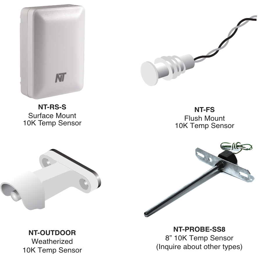
ADDING EXTERNAL SENSOR PROBES
Add the NT-RS-S or NT-FS to the NT-URS by connecting two wires from the probe to the terminals designated 1 and 2 on the NT-URS. (Connection to NT-RS-S shown below)
The wires can be connected with either polarity. Use 2-conductor cable (22AWG minimum) with a maximum length of 300 feet (or 90m).
IMPORTANT: If the NT-URS is initially configured with an external probe and the probe fails or is disconnected, the NT-URS will stop reporting and the Diagnostic LED will continually light until the problem is corrected.
NT-RS-S connected to NT-URS Sensor

(Optional NT-FS connection not shown)
Available Sensor Probes from Network Thermostat
NT-URS AS AUX1, AUX2, OR AUX3 SENSOR
The NT-URS can report as an AUX1, AUX 2, or AUX3 sensor. In this configuration, you can use either the internal temperature sensor or an external probe.
When the NT-URS is initially detected by the thermostat, it will check first from the external probe connections, if no probe is detected, the sensor will default to the internal temperature sensor.

IMPORTANT: If the NT-URS is initially configured with an external probe and the probe fails or is disconnected, the NT-URS will stop reporting and the Diagnostic LED will continually light until the problem is corrected.
Multiple Indoor Sensor Configuration
You can connect up to six (6) NT-URS sensors to provide INDOOR temperature averaging in a large area or several zones being controlled by the same system. The maximum distance for all sensors is 300 ft. (90m). Follow the instructions and diagrams to connect the additional INDOOR sensors.
NOTE:: Only ONE (1) NT-URS sensor configured as an INDOOR sensor can be added in this manner. Additional INDOOR sensors may be added by using the AVG terminals.
Wire the first sensor using the single sensor instructions.

CAUTION: Make sure there is no power to the sensors by removing the thermostat from its backplate.

Connect wires to each additional sensor in the following manner.

- Set #SENSORS jumper to 1-2 for ALL additional sensors used for averaging.
Reinstall the thermostat faceplate onto its backplate. Check proper operation by watching the LED blink pattern as outlined in the LED Status section. Repeat for each sensor.

One (1) Year Limited Warranty
Network Thermostat™ warrants to the original purchaser that this product will be free from defects in workmanship and materials for five years from the date of purchase with proof of purchase.
Warranty Limitations
This warranty begins on the date of purchase.
Warranty is Void if:
- The date code or serial number is defaced or removed.
- The product has a defect or damage due to product alteration, connection to an improper electrical supply, shipping and handling, accident, fire, flood, lightning, or other conditions beyond the control of the manufacturer.
- The product is not installed according to the manufacturer's instructions and specifications.
Owner’s Responsibility
- Provide proof of purchase.
- Provide normal care and maintenance.
- Pay for freight, labor, and travel.
- Return any defective product.
- In no event shall the manufacturer be liable for incidental or consequential damages.
This warranty gives you specific legal rights and you may have others that vary by state and/or province. For example, some states and/or provinces do not allow the exclusion or limitation of incidental or consequential damages, so this exclusion may not apply to you. The manufacturer’s continuing commitment to quality products may require a change in specifications without notice.
Specifications
Rated Voltage:
20V to 30VAC, 24VAC nominal
Internal Temp Sensor Range:
+28°F to 119°F in 1° steps (-2°C to 48°C in 1° steps)
External Temp Sensor Range:
Outdoor: -54°F to +119°F (-48°C to +48°C);
Auxiliary Temp Sensor Range:
AUX1, AUX2, AUX3: -40°F to +200°F (-40°C to +93°C)
Internal Humidity Sensor Range:
5% to 95% Relative Humidity, Non-condensing
Measurement Accuracy:
Temperature: ± 1.0°F (±0.5°C);
Humidity: 0-90%RH (±3%) ; 20-80% RH (±2%)
Terminations:
RS1 - Data, RS+V – Power, RS2 – Return, 1 & 2 – External Temp Sensor Leads, 1-2, 3-5, 6+ Sensors
Dimensions:
2.1”H x 2.85”W x 1.0”D (53mm x 73mm x 25.4mm)
Approved Cable Types:
CAT5 or CAT5e unshielded, or 1-Pair Twisted Shielded Cable with Drain and nominal capacitance of 12pF/ft or less. Use a riser or plenum jacket as required by the local code.
Maximum 300ft Total Sensor Cable Length per Thermostat
LED Status
The NT-URS includes a Diagnostic LED that can help you troubleshoot your installation and sensor operation.
LED Off:
LED OFF indicates no power to the NT-URS or thermostat. Check the wiring of your sensor and the thermostat for problems. Fix as necessary.
LED On Solid During Power-Up:
On power-up, the LED will turn on solid until the NT-URS successfully communicates with the thermostat. If the connection is successful, the LED will blink according to its configuration. If the remains on, there is a communication problem. Check the wiring and fix it as necessary.
LED On Solid After Power Up:
If the NT-URS loses connection with the thermostat for 60 seconds, the LED will turn on solid. Check the wiring and fix it as necessary. Cycle the power and recheck the LED status.
LED Slow Blink (Onboard Sensor Operation):
If the NT-URS is configured to use its internal sensor (temperature or humidity) the LED will blink each time the thermostat requests data. This occurs approximately every 16-20 seconds.
LED Double Blink (Onboard Sensor Averaging):
If the NT-URS is configured to INDOOR temperature and an additional sensor is connected to the AVG connection, the LED will blink twice each time the thermostat requests data. This occurs approximately every 16-20 seconds.
LED Triple Blink (External Probe Operation)
If the NT-URS is configured to use an external probe connected to the 2-screwless terminals, the LED will blink three times the thermostat requests data. This occurs approximately every 16-20 seconds.
LED Fast Continuous Blink (Lost External Probe)
If the NT-URS is configured to use an external probe and the NT-URS loses communication with the probe, the LED will continually blink fast. Check wiring and external probe and fix as necessary.
NOTE: In this condition, the NT-URS will stop reporting until the communication with the external probe is fixed.
Wiring Diagram

Compatibility Chart

DIP Switch SETTINGS
