
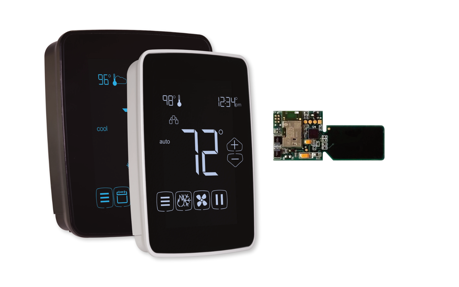
Before You Start
Please read the entire installation manual. The thermostat will need to be correctly wired and configured for proper operation. Basic HVAC configuration can be performed from the thermostat touchscreen and advanced settings are accessed via your network and the Internet.
Warning: Turn off power to the HVAC equipment before opening the thermostat or handling the module. Failure to do so may damage the thermostat or HVAC equipment.
NOTE: Installation must be performed by a qualified HVAC technician or licensed electrician familiar with low-voltage control wiring.
Table of Contents
- Introduction
- What is in the box?
- X-Series Thermostat Module Installation
- X-Series Thermostat Retrofit Module Installation
- J-Series Thermostat Module Installation
- Accessing The Installer Menu
- Configuring Occupancy Input
- Soft Setback Configuration
- Web Interface — Fine-Tuning Occupancy Settings
- Bluetooth Radio Reset
- TruBlu™ Network Commissioning
- Five (5) Year Limited Warranty
Introduction
The NT-BT-MOD-SR is a Bluetooth mesh radio module that installs into the NetX-Expansion slot of compatible NetX™ X-Series and J-Series thermostats. Once installed, it allows the thermostat to operate as a Bluetooth Mesh Sensor Client, subscribing to real-time occupancy data published by sensors already present in a TruBlu™ NLC lighting network — no additional wiring or dedicated occupancy sensors required.
The module works in conjunction with the thermostat's Soft Setback feature to automatically adjust heating and cooling setpoints based on detected occupancy, reducing energy consumption during unoccupied periods while ensuring comfort is restored when occupants return.
What is in the box?
(1) NT-BT-MOD-SR
(1) Retention Clip (Optional on X-Series Retrofits)
NOTE: The retention clip is NOT required for J-Series thermostats. The NetX-Expansion slot design retains the module without additional hardware.
X-Series Thermostat Module Installation
1. Power down: Turn off power to the HVAC equipment at the breaker or disconnect.
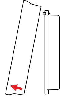
2. Remove the faceplate: Grasp the thermostat firmly near the bottom and gently pull the faceplate away from the backplate. Set the faceplate face-down on a clean, flat surface.
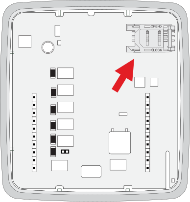
3. Locate the NetX-Expansion slot: The expansion slot connector is located in the upper-right area of the circuit board interior.
4. Unlock the Retaining Latch: Slide the plastic retaining latch in the direction indicated by the UNLOCK arrow, away from the LOCK position. You will feel or hear a slight click as the bracket releases.
Caution: Do not use excessiveforce. The latch slides with minimal resistance when properly disengaged.
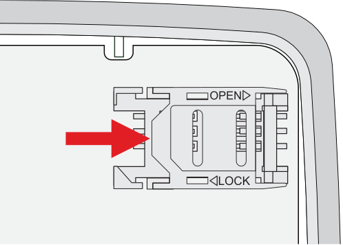
5. Open the Retaining Bracket: Lift the hinged retaining bracket upward into the open/tilted position, revealing the internal guide tracks and contact area beneath. The bracket should remain open on its own while you prepare the module.
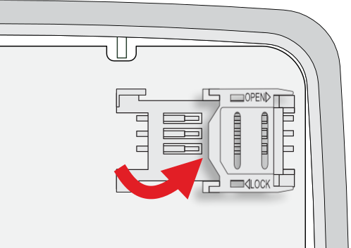
6. Insert the Module: Slide the edge of the NT-BT-MOD-SR module into the guide tracks of the open retaining bracket. The module inserts into the tilted bracket — not directly flat onto the board. Slide it fully until firmly and evenly seated. Do not force it; it should slide smoothly when properly aligned.
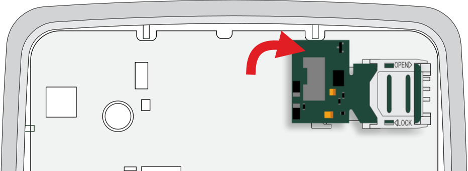
7. Close the Assembly: Gently swing the retaining bracket (with the module seated inside it) downward until it lies flat against the circuit board. The module's contact pads should align with the connector's contact pins on the PCB.
Caution: Ensure the module is lying flat and properly aligned before proceeding to lock. An improperly seated module may damage the connector contacts if locked in a misaligned position.
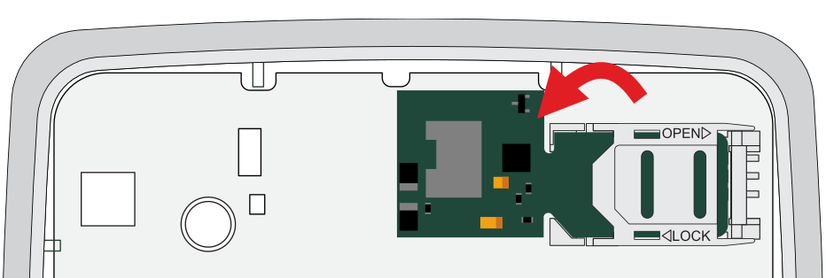
8. Lock the Retaining Latch: While holding the bracket flat with one finger, slide the retaining latch in the direction indicated by the LOCK arrow until it clicks firmly into the locked position. The module is now secured.
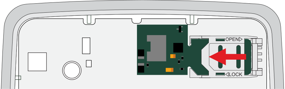
9. Verify Installation: Confirm that:
• The module sits flat and flush with no lifting or rocking.
• The retaining latch is fully engaged in the LOCK position.
• No visible misalignment or component interference is present.
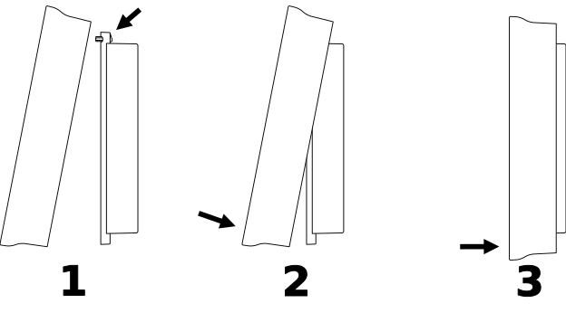
10. Reattach the faceplate. Place the top of the faceplate over the top lip of the backplate, swing it down, and press the bottom center edge until it snaps firmly into place.
11. Restore power. Turn power back on at the breaker or disconnect.
TIP: After restoring power, navigate to the thermostat's Installer Menu to confirm the Bluetooth module is recognized and active.
X-Series Thermostat Retrofit Module Installation
NOTE: If your thermostat’s NetX Expansion Port resembles the one in the illustration below, you will need to install a provided retention clip to ensure proper installation. Follow the instructions below for this thermostat version.
1. Power down. Turn off power to the HVAC equipment at the breaker or disconnect.
2. Remove the faceplate. Grasp the thermostat firmly near the bottom and gently pull the faceplate away from the backplate. Set the faceplate face-down on a clean, flat surface.
3. Locate the NetX-Expansion slot. The expansion slot connector is located in the upper-right area of the circuit board interior.
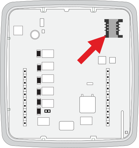
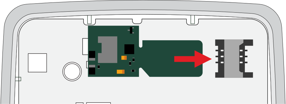
4. Orient the module. Hold the NT-BT-MOD-SR with the antenna tab to the right and the edge connector facing the expansion slot connector.
5. Insert and slide. Place the module into the bay at the left side and slide it to the right until the edge connector is fully engaged in the expansion slot.
6. Verify seating. The module should lie flat and flush. The edge connector should be fully engaged with no visible gap.
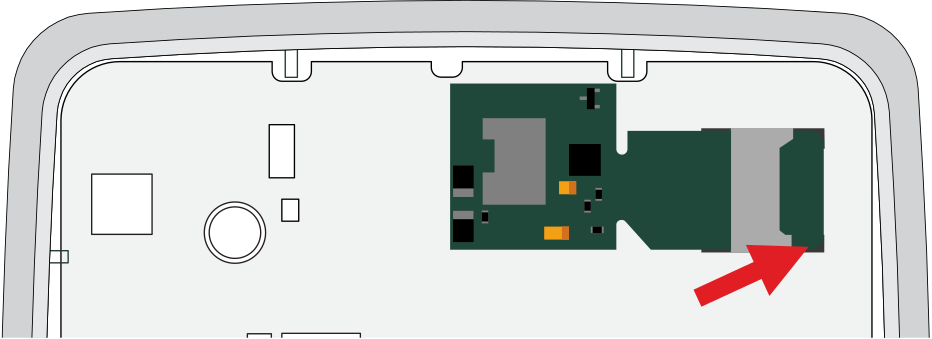
7. Place the retention clip. Position the retention clip against the left edge of the module. The stopper braces the module and prevents it from backing out of the connector once seated.
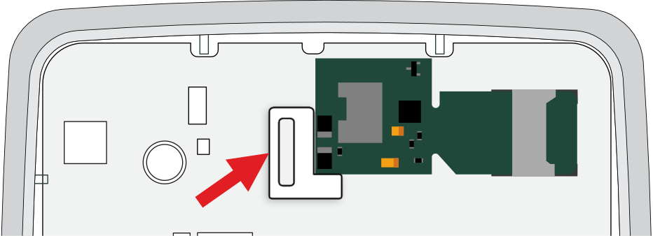
8. Reattach the faceplate. Place the top of the faceplate over the top lip of the backplate, swing it down, and press the bottom center edge until it snaps firmly into place.
9. Restore power. Turn power back on at the breaker or disconnect.
TIP: After restoring power, navigate to the thermostat's Installer Menu to confirm the Bluetooth module is recognized and active.
J-Series Thermostat Module Installation
1. Power down: Turn off power to the HVAC equipment at the breaker or disconnect.
2. Remove the faceplate: Grasp the thermostat firmly near the bottom and gently pull the faceplate away from the backplate. Set the faceplate face-down on a clean, flat surface.
3. Locate the NetX-Expansion slot: The expansion slot connector is located in the upper-right area of the circuit board interior.
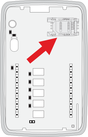
4. Unlock the Retaining Latch: Slide the plastic retaining latch in the direction indicated by the UNLOCK arrow, away from the LOCK position. You will feel or hear a slight click as the bracket releases.
Caution: Do not use excessive force. The latch slides with minimal resistance when properly disengaged.
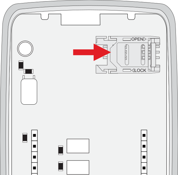
5. Open the Retaining Bracket: Lift the hinged retaining bracket upward into the open/tilted position, revealing the internal guide tracks and contact area beneath. The bracket should remain open on its own while you prepare the module.
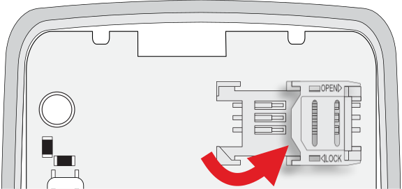
6. Insert the Module: Slide the edge of the NT-BT-MOD-SR module into the guide tracks of the open retaining bracket. The module inserts into the tilted bracket — not directly flat onto the board. Slide it fully until firmly and evenly seated. Do not force it; it should slide smoothly when properly aligned.
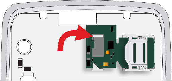
7. Close the Assembly: Gently swing the retaining bracket (with the module seated inside it) downward until it lies flat against the circuit board. The module's contact pads should align with the connector's contact pins on the PCB.
Caution: Ensure the module is lying flat and properly aligned before proceeding to lock. An improperly seated module may damage the connector contacts if locked in a misaligned position.
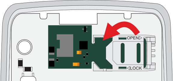
8. Lock the Retaining Latch: While holding the bracket flat with one finger, slide the retaining latch in the direction indicated by the LOCK arrow until it clicks firmly into the locked position. The module is now secured.
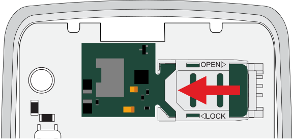
9. Verify Installation: Confirm that:
• The module sits flat and flush with no lifting or rocking.
• The retaining latch is fully engaged in the LOCK position.
• No visible misalignment or component interference is present.
10. Reattach the faceplate. Place the top of the faceplate over the top lip of the backplate, swing it down, and press the bottom center edge until it snaps firmly into place.
11. Restore power. Turn power back on at the breaker or disconnect.
TIP: After restoring power, navigate to the thermostat's Installer Menu to confirm the Bluetooth module is recognized and active.
Accessing The Installer Menu
Module configuration is performed from the thermostat's Installer Menu. Access requires an unlocked faceplate (the lock icon must not be displayed on the main screen).
1. Confirm the thermostat faceplate is unlocked. If the screen is locked, enter the 4-digit PIN to temporarily unlock it before proceeding.
2. Press and hold the Menu Button (lower-left of touchscreen) for approximately 5 seconds.
3. Release the button when Installer appears briefly in the dot matrix display, followed by a firmware version number.
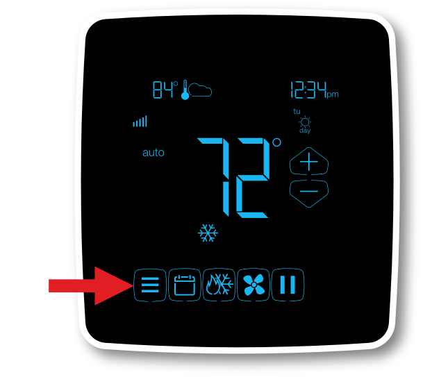
4. Use the Up and Down Buttons to navigate between menu items, the Checkmark Button (Right Arrow) to enter and confirm a setting, and the Back Button (Left Arrow) to return to the previous item.
NOTE: The Up and Down Buttons adjust the value of the selected parameter. Press Checkmark Button (Right Arrow) to save and advance to the next menu item.
Configuring Occupancy Input
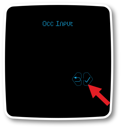
From the Installer Menu, navigate forward using the Checkmark Button (Right Arrow) until Occ Input is displayed.
1. At Occ Input, press Up to cycle through the options until Occ Module is displayed.
2. Press the Checkmark Button (Right Arrow) to confirm and advance.
NOTE: Occupancy Input Options
• Occ None
• Occ Module
• Occ Terminal (X-Series only)
• Occ UI1 Input (Available on J5T models only)
Soft Setback Configuration
After setting Occ Module, continue through the Installer Menu to configure the Soft Setback parameters. These settings control how the thermostat responds to states in both occupied and unoccupied HVAC schedule periods reported by the Bluetooth radio module.
Soft Setback:
Options: Setback Off [default], Setback On
When Setback On, raises the cool setpoint and lowers the heat setpoint by the Setpoint Offset amount when the space is unoccupied during a scheduled occupied period. Setpoints return to normal when occupancy is detected.
Occ Recovery (Occupied Recovery):
Options: Off [default], Soft, & Full
Soft Recovery: when occupancy is detected during an unoccupied schedule, setpoints revert to the last occupied values adjusted by the Setpoint Offset.
Full Recovery: setpoints fully return to the last occupied values without adjustment.
In both cases, the thermostat reverts to the unoccupied schedule when the sensor reports unoccupied.
Setpoint Offset
Options: 2°–8°F (1°–4°C) in 1°F (0.5°C) steps. [Default 2˚F (1˚C)]
Degrees by which Soft Setback and Soft Recovery adjust the setpoints. Visible only when Soft Setback is Setback On or Occ Recovery is Soft Recovery.
Verify Occ Delay (Verify Occupancy)
Options: 0–10 minutes in 0.5-minute steps. [Default 2.0 minutes]
How long the sensor must continuously detect occupancy before the thermostat begins an occupied state. Prevents brief motion events from triggering conditioning.
Min Occ Time (Minimum Occupied)
Options: 0–30 minutes in 0.5-minute steps. [Default 10 minutes]
Minimum duration the occupied state will remain active once triggered, regardless of whether motion continues to be detected.
Unocc Delay (Verify UNOccupancy)
Options: 0–30 minutes in 0.5-minute steps. [Default 10 minutes]
How long before the thermostat returns to an unoccupied state after no motion is detected.
NOTE: If Min Occ Time is set shorter than the Unocc Delay, occupied behavior effectively follows the Unocc Delay timer after no motion is detected. To guarantee a minimum run period regardless of motion drop-off, set Min Occ Time higher than Unocc Delay.
Saving and Exiting
1. After confirming Unocc Delay, continue pressing the Checkmark Button until Exit Menu is displayed.
2. Press the Checkmark Button to save all changes and return to the main thermostat operating screen.
Web Interface — Fine-Tuning Occupancy Settings
After initial configuration via the Installer Menu, all Soft Setback parameters can also be reviewed and adjusted through the thermostat's built-in web server (DirectConnect™) or via NetX-Cloud™. Navigate to the Sensor Settings page and locate the Occupancy section. The web parameter names correspond to the Installer Menu items in the instructions above.
Bluetooth Radio Reset
If the module does not appear in the TruBlu™ network, or if you are re-commissioning the thermostat into a new or existing mesh network, perform a Bluetooth Radio Reset from the Installer Menu. This resets only the Bluetooth module — all HVAC settings and schedules are preserved.
1. Access the Installer Menu
2. Navigate forward through the menu items using the Checkmark Button until Exit Menu is displayed.
3. At Exit Menu, press Up to enter the Reset Options submenu.
4. Press Up to cycle through the reset options until BT Radio Reset? is displayed.
5. Press the Checkmark Button to select. The display will show Are You Sure?
6. Press the Checkmark Button again to confirm. The display will show Resetting…
7. The thermostat will automatically reboot and return to the main operating screen. The Bluetooth module is now reset and ready for commissioning.
Warning: Performing a BT Radio Reset will remove the thermostat from any TruBlu™ mesh network it was previously commissioned into. You must re-commission the thermostat following the steps in TruBlu™ Network Commissioning after performing this reset.
TruBlu™ Network Commissioning
After the module is physically installed and the thermostat is configured, the thermostat must be commissioned into the TruBlu™ Bluetooth mesh network using the TruBlu™ web and mobile apps. This process creates and links thermostat zones to occupancy zones in the lighting network.
Refer to the following mwConnect document for complete commissioning procedures:
TruBlu Network Commissioning Instructions
Commissioning Overview
1. Create thermostat zones in the TruBlu™ web app. Each zone containing the thermostat must use a profile based on Occupancy Sensing or Vacancy Sensing (with or without daylight harvesting).
2. Link thermostat zones to occupancy zones. In Zone Linking, assign the occupancy zones whose sensors will activate the HVAC system.
3. Add the thermostat to its zone on-site using the TruBlu™ mobile app.
4. Verify operation. Trigger occupancy in a linked zone and confirm the thermostat transitions to the occupied state within the configured Verify Occ Delay period.
NOTE: All occupancy zones linked to a thermostat zone must use a sensor profile that includes occupancy or vacancy sensing. Zones using daylight-only profiles will not generate occupancy events.
Five (5) Year Limited Warranty
Network Thermostat™ warrants to the original purchaser that this product will be free from defects in workmanship and materials for a period of five years from the date of purchase with proof of purchase.
Warranty Limitations
This warranty begins on the date of purchase.
Warranty is Void if:
The date code or serial number is defaced or removed.
The product has a defect or damage due to product alteration, connection to an improper electrical supply, shipping and handling, accident, fire, flood, lightning, or other conditions beyond the control of the manufacturer.
The product is not installed according to the manufacturer’s instructions and specifications.
Owner’s Responsibility
• Provide proof of purchase.
• Provide normal care and maintenance.
• Pay for freight, labor, and travel.
• Return any defective product.
• In no event shall the manufacturer be liable for incidental or consequential damages.
This warranty gives you specific legal rights, and you may have others that vary by state and/or province. For example, some states and/or provinces do not allow the exclusion or limitation of incidental or consequential damages, so this exclusion may not apply to you. The manufacturer’s continuing commitment to quality products may require a change in specifications without notice.
CA Title 24 Requirements
This thermostat meets the Joint Appendix 5 (JA5) requirements for Occupant Controlled Smart Thermostat (OCST) certification of the California Energy Commission (CEC).
FCC Regulatory Information
This equipment has been tested and found to comply with the limits for a Class B digital device, pursuant to part 15 of the FCC Rules. These limits are designed to provide reasonable protection against harmful interference in a residential installation. This equipment generates, uses, and can radiate radio frequency energy, and if not installed and used in accordance with the instructions, may cause harmful interference to radio communications. However, there is no guarantee that interference will not occur in a particular installation. If this equipment does cause harmful interference to radio or television reception, which can be determined by turning the equipment off and on, the user is encouraged to try to correct the interference by one or more of the following measures:
• Reorient or relocate the receiving antenna
• Increase the separation between the equipment and the receiver
• Connect the equipment to an outlet on a circuit different from that to which the receiver is connected
• Consult the dealer or an experienced radio/TV technician for help
Copyright Notice
This manual and its content are the copyright of Network Thermostat.
© Network Thermostat 2026. All rights reserved.
Specifications